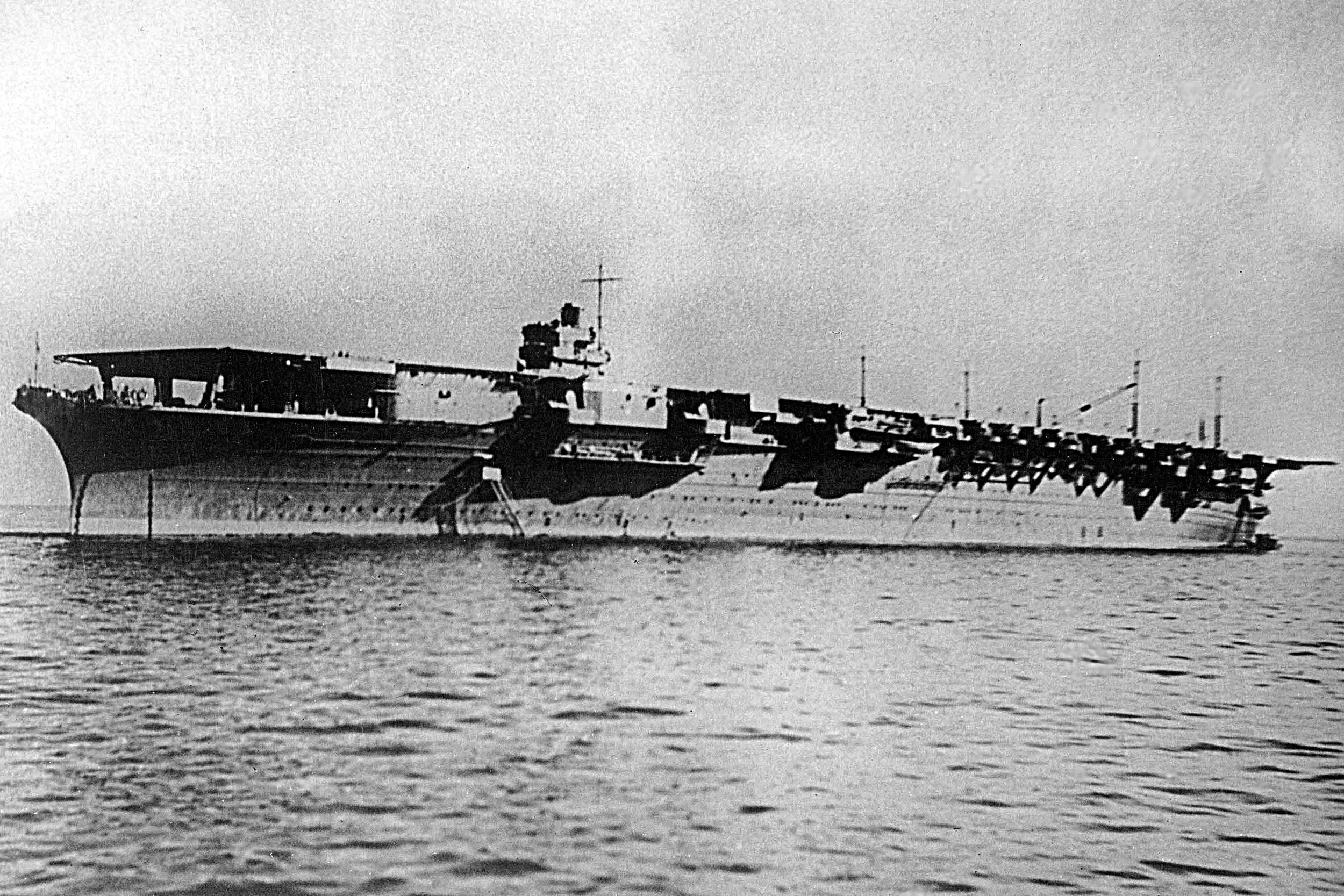
The Japanese armoured flight deck aircraft carrier Taiho, pictured between May 15-16, 1944, at Tawitawi, Borneo. A Shokaku class carrier is in the background.
DOCTRINE DETERMINED
Taiho was the Japanese Navy’s last pre-war carrier design.
It represented a radical departure from established doctrine
Taiho, in many ways, mirrored the application of the philosophy that produced the battleship Yamato. Japan had given up the idea of achieving numerical fleet parity with the United States. So it sought to gain a decisive qualitative edge.
While naval aviation was the one area Japan strove to maintain equal numbers, it also sought to ensure its new ships would have greater survivability than their US counterparts.
Like Britain and the United States, Japan had become increasingly concerned at the lessons being delivered by extensive war gaming.
Carriers were immensely vulnerable weapons. The ship that failed to get in the first strike was usually the first to be sunk. And the carrier was obviously unsuited to sea battles: Any hit on her hangar or flight deck could instantly render her inoperative.
How could this be mitigated?
Like the Royal Navy, Japan looked at improving their carriers’ passive defences.
Namely, armour on the flight deck.
But comparisons with Britain’s Illustrious class are not entirely valid. Taiho was built to a significantly different concept, in many ways closer to the later US Midway design.
Close waterways under the constant umbrella of land-based aircraft, such as the Mediterranean, were not a concern.
Instead, Japan saw the armoured carrier as playing a role in a multi-layered fleet.
Taiho represented what Japanese doctrine determined to be a 1st line of aircraft carriers. These would be closer to the enemy – exposed and subject to attack.
The older unarmoured carriers formed the 2nd line, sitting further behind. From this safe position they would await a 'trigger' strike on the 1st line to expose the location of opposing forces so they could launch a devastating counterstrike.
But Japan also wanted the maintain the capability of a viable first-strike from its armoured carriers. And this needed ships much larger than treaties would allow.
IJN Shokaku represented the template upon which future Japanese fleet carrier designs were based.
ORIGINS

Japan had abandoned the various international naval treaties by 1936. The Royal Navy, however, was still bound by separate agreements with Germany and Italy.
As a result, it approached the design of Taiho without any of the limitations RN design staff were struggling with.
In 1936, Japan formulated a policy which sought to field 12 battleships, 10 aircraft carriers, 20 armoured cruisers and 8 light cruisers. It was overly ambitious.
Design work on Project W02 (later W102) began as early as 1937, with the first drawings submitted in November.
The outline was for a 33,600 ton ship, 250m long by 27.7m wide. Her top speed was to be 33.4kts with a range of 10,000 nautical miles at 18knots. Armament was to be 6x twin 10cm AA, and 8x triple 25mm mounts. Her air group was to be 18+3 (reserve) Type 96 fighters, 18+3 Type 96 bombersand 21+1 Type 97 torpedo bombers. This was a total air group of 57 active and 7 spare aircraft. The deck park would hold 7 bombers and 5 torpedo planes.
This ship had an upright funnel and an open forecastle with no hurricane bow.
But the design then entered a phase of protracted development. The outcome would become Japan’s most advanced purpose-built carrier.
The new carrier was approved on December 8, 1938 but detailed design work did not begin until December 1939 – designated Project G-13. After a string of delays, possibly due to lessons learnt from RN and German war experience, she was only laid down on July 10, 1941.
The ship that finally emerged was very different to what had originally looked like a slightly modified Shokaku.

ENTER TAIHO
On March 5, 1943, the new design – Construction number 130 - was named Taiho (Grand Phoenix).
She was considerably larger than Illustrious and her later sisters at 29,300 tons standard / 37,270 tons deep load. She was to carry some 1751 crew.
She had an unusually large island for a Japanese carrier. She also had an enclosed ‘hurricane’ bow – and radar.
But she wasn’t quite right. The Japanese navy considered the Shokaku class to be the baseline for all future carriers. And Taiho was comparatively under-armed.
So two slightly improved Taiho’s were listed in the 1942 construction program – Hulls 801 and 802.
The revised design boosted the number of heavy anti-aircraft mounts from six twins to eight twins. To accommodate these and their ammunition stores the length of the ship was extended (the new flight deck was 4m longer), and resulted in an overall displacement some 1600 tons heavier.
Production of five of these new improved Taiho’s was proposed in late 1942 (Hulls 5021-5). One was ordered, though none was ever laid-down. Expected completion dates were, by now, not before 1947-48.
Taiho was launched on April 7, 1943. She was commissioned into active service on March 7, 1944.
Many of her crew were veterans of Zuikaku. Much of the remainder were freshly trained.

Click on the image to be taken to the artist's web page.
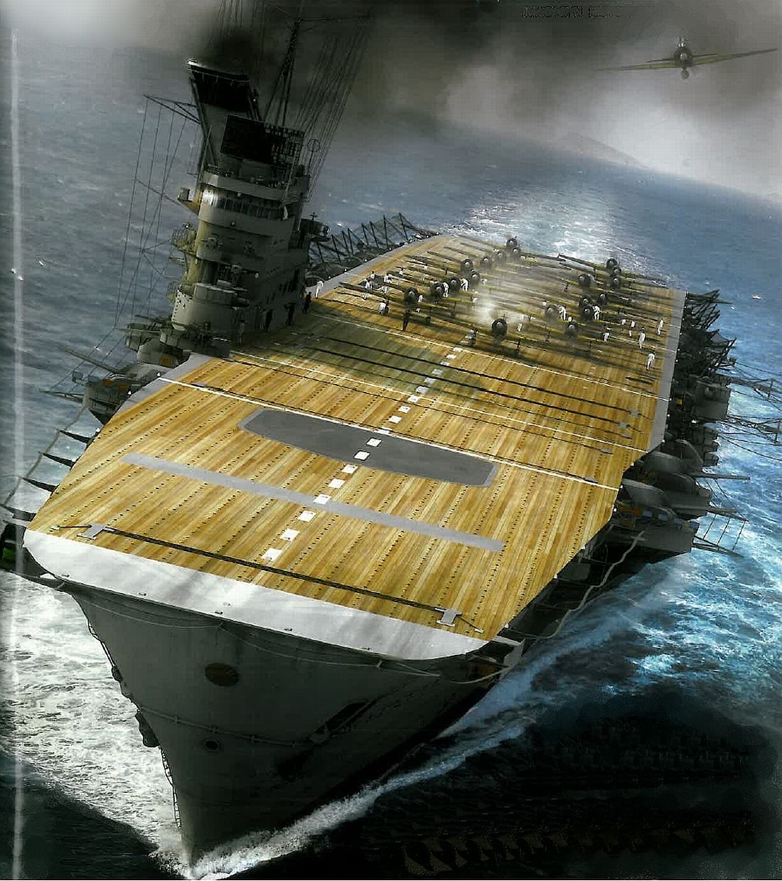
FLIGHT DECK
Overall, the flight deck was 843ft (257m) long and 98ft 6in (30m) wide, though the width varied from 18m in the forward section, 30m amidships and 27m aft. At the island the deck was 29m wide.
The only Japanese carrier to have a greater flight deck area was Shinano.
It was also offset 6.6ft (2m) to port to balance the weight of what was an unusually large island for a Japanese carrier.
Where the British built their Illustrious class with an armoured box hangar integrated into a flight-deck strength-deck design, the Japanese provided Taiho with a simple armoured ‘lid’ between the two lifts – some 150m long and 19.7m wide.
This varied between 2.95in (75mm) and 3.14in (80mm) thick CNC armour on top of supporting 20mm DS plates – for an average of 95mm (3.7in). Japanese calculations estimated this was capable of stopping a 1100lbs (500kg) bomb and 200mm (8in) shells.
Like Illustrious, Taiho had structural provisions to absorb the shock of a bomb: in her case 70cm high box-shaped deck beams. An additional 10mm DCS plate was fixed to the bottom of these to protect them from splinter damage.
There is some debate as to whether or not this steel flight deck was covered with timber planks or a latex coating some 0.24in (.6cm) thick. It is possible Taiho carried both, with the coating being applied at some point after her completion.
Taiho’s flight deck was some 12.51m above the waterline in standard load, 12m in full load.
This represents Japan’s struggle to cope with the weight of such armour high in the ship. Taiho was completed with one deck less than what was considered the ideal template – the Shokaku class.
From Encyklopedia Okretow Wojennych 39: Taiho Volume 1
HANGARS

Taihio had a two-storey hangar arrangement from the earliest of her design drawings.
Ultimately she was completed with both decks only just short of 500ft with an effective height of 16ft 6in. The upper hangar averaged 150m by 18m by 5m, and the lower hangar 150m by 17m by 5m.
Unlike the Royal Navy and the United States, the Japanese had no particular doctrine relating to the design of their hangars. But they had found open hangars failed to keep out green seas and were not ‘light tight’ at night.
As a result, generally, Japanese hangars were enclosed. But they were not flash-tight or vapour-tight, as were the RN hangars.
Taiho’s hangar sides were only lightly protected against splinters: the upper hangar had 25mm CNC side plates while the lower had 16mm on the port side and 18-20mm on the starboard side.
These were supposed to be water-tight.
This armour was arranged to reduce the damage to the flight deck if a bomb exploded within the hangar itself – or if aviation fuel vapour exploded. To this end, the hangar sides were given 1.5m by 0.7m slits (covered by 25mm armoured shutters) which were supposed to vent the force of any blast.
No armour was placed on the floor of the upper hangar deck. On the lower hangar deck, over the engine and boiler rooms – as well as the aft magazines – was 16mm DS plate with 32mm CNC on top. This was thickened to 75mm CNC over the forward magazine.
While the armoured flight deck gave the ship substantial rigidity, it was not the strength deck as with the Illustrious class. Instead, Taiho’s main strength member was the lower hangar deck. Either way, the weight of Taiho’s armour resulted in the lower hangar deck being barely above the waterline in full-load condition.
During her limited service, Taiho tended to stow her fighters in the middle and forward section of the upper hangar. This allowed rapid access to the forward lift from which the light aircraft could be quickly manhandled into position.
Dive bombers generally filled the remainder of the upper hangar, with the lower hanger used for the larger torpedo bombers. As both types were heavier than fighters, and needed greater take-off-lengths, it was faster for them to be arranged via the aft lift.
From Encyklopedia Okretow Wojennych 39: Taiho Volume 1
LIFTS
Taiho was completed with just two lifts, not the three earlier Akagi, Kaga, Hiryu, Soryu, Shokaku and Zuikaku. This significant alteration in flight deck design was a direct response to the weakness in the flight deck structure such a three-lift arrangement had proven to generate.
However, Taiho’s 100ton lifts were roughly double the size of those used aboard Illustrious. This was because Japanese naval aircraft design had not produced a comprehensive wing-folding system. Fighters and bombers could generally only tuck away their wingtips.
Both lifts were roughly pentagonal in shape, with the aft elevator being 45ft 11in (14m) long and 45ft 11in (14m) wide. The forward elevator was slightly narrower, at 13.6m.
The aft lift was offset to starboard of the centreline. A retractable derrick could be tucked into the flight deck alongside. Its 4.1ton capacity was for the recovery and stowage of float planes, but may have also offered some capacity to move aircraft that crashed on landing.
Taiho also was built to operate significantly heavier aircraft than earlier IJN carriers. Her lifts were stressed for up to 16,500lbs (7500kg). Most earlier Japanese carriers could only hoist 4500kg (5 tons).
Their cycle time was 15 seconds to hoist an aircraft from the lower hangar, with a similar time to return.
These lift platforms were not substantially armoured. Two 25mm DS armoured plates again offered a degree of splinter protection along with increased structural rigidity.
Also like the British, the Japanese navy powered its lift hoists electrically. The USN relied on hydraulics.
But Taiho’s lift wells, in full-load condition, actually extended below the waterline.
Standard operating procedure was to keep the lifts lowered if aircraft were being refuelled in the hangars to improve ventilation to draw-out fuel fumes.
ARRESTER GEAR

Unlike British and American hydraulic arresting systems, the Japanese used an electric deceleration mechanism. Like the British and Americans, however, each unit was attached to two wires in order to reduce the number of units required.
Fourteen wires were arrayed between the fore and aft elevators at intervals of 9.3m.
While originally intended to carry the new Kusho Type 10 design arresting mechanisms, a modified version older Type 4 was reverted to due to supply problems.
Taiho, built to operate much newer and heavier aircraft, was able to trap 13,200lb aircraft at 78 knots on each of its six forward and eight aft wires.
Two crash barriers were positioned at the aft end of the island, and a third at the forward end.

Click on the image to be taken to the artist's web page.
CATAPULT

While Japan had adopted a German catapult design to launch seaplanes from its battleships and cruisers, it did not build such assisted take-off gear into its carriers.
The thinking was it possessed aircraft with particularly strong take-off performance, and its fleet carriers were large enough to accommodate longer take-off runs by heavier machines.
This was fine – until Japan started losing its larger carriers and the pressures of technological advancement produced bigger and heavier aircraft.
By the time Taiho entered service, the Japanese Navy found itself in something of an embarrassing situation. And carrier catapults – as modern Russian, Chinese, Indian designs (as well as the USS Ford) demonstrate – present more than just minor technical challenges.
Taiho was intended to have two catapults built into its bow. But by the time she was completed, a workable design was simply not available.
By the end of the war, the Japanese Navy was compelled to use obsolete aircraft as these were the only ones capable of flying-off from the surviving smaller carriers.
While rocket-assisted take-off gear was developed capable of providing 1500lbs (700kg) of thrust for three seconds, like the Royal Navy the Japanese found this system simply too unreliable for regular use.

A close-up from a photo higher on this page of Taiho, between May 15-16, 1944, at Tawitawi, Borneo.
FIRE SUPPRESSION

Unlike the Illustrious Class, Taiho did not use a water displacement system for the storage of its aviation fuel. Instead, the fuel tanks were integral with the structure of the ship. While surrounded by space filled with inert carbon dioxide gas to reduce the chances of explosive vapour from forming, the integrity of this space was entirely dependent upon the ship’s ability to absorb the shock of a bomb, mine or depth-charge.
As the battle of Midway had demonstrated, this proved to be a flawed concept.
Notably, the bottom of Taiho’s lift wells formed part of the roof to its two AvGas storage spaces.
Spilled AvGas vapour tended to gather no more than 6ft off deck level. Open hangar ships did not need any mechanism to remove this gas build-up. British enclosed hangars used natural flow from the two lifts, as well as low-powered, low-positioned exhauststo draw it out. Electrical outlets and lights were also generally positioned some 8ft above the hangar floor level to avoid dangerous sparks.
Initially Japan’s powerful intake and exhaust fans tended to only mix the AvGas vapour to dangerous levels with the atmosphere inside the hangar. By the time Taiho was completed, however, this mistake had been realised and largely mitigated.
If a fire was experienced, Taiho’s was fitted with two rows of pipes on the walls and ends of hangars to smother the space with suppressant soap-foam. These were controlled from fireproof lobbies.
The lower hangar could also be flooded with carbon dioxide, as Japanese naval architects felt this space was the most likely to suffer fuel vapour build-up.
The upper hangar was divided into five spaces by horizontally-retractable fire curtains made from rockwool/asbestos. The lower hangar could be sectioned into four spaces.
As with the British carriers, these curtains served both to block the spread of fire as well as reduce the supply of air.
The lift wells could be closed off from the hangar by 7mm steel fire barriers, also clad with asbestos.

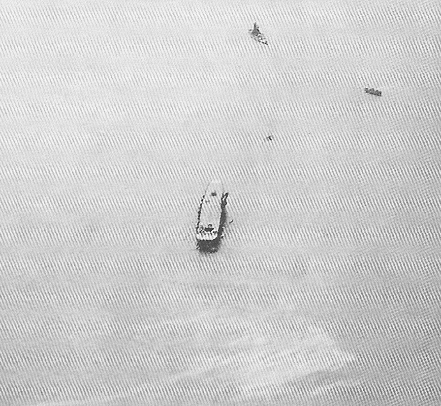
A poor quality image, but the only known image showing the ship from overhead on the bows, of IJN Taiho at Tawitawi, Borneo.
PROTECTION

Overall, Taiho was completed with 8800 tons of armour representing 30 per cent of the total weight of the ship. Only the converted Yamato-class battleship Shinano had a greater proportion of its weight to protection.
Japanese Naval General Staff requirements were for protection against 500kg bombs on the flight deck, delivered by dive bombers. Protection from 1000kg armour piercing bombs dropped horizontally from 3000m and against 20cm (8in) armour piercing shells fired from 12,000 to 20,000m.
The deck, as previously stated, was given 3in CNC armour between the lifts at 19.7m width. Outside of this area, the lower hangar deck was fitted with of 20mm DS plates supporting 75mm to 90mm NVNC plates.
Taiho’s inclined armoured belt at the waterline averaged 2.2in (55mm) CNC in thickness alongside the machinery spaces. The forward magazine was covered by 165mm-80mm NVNC armour. The aft magazine had 130mm to 75mm NVNC.
The ammunition chambers were capped by 75mm armour plates. The main steering room had 125mm NVNC armour plat both on its sides and above it.
Notably, the aviation fuel storage spaces were only partially encompassed by 50mm-60mm CNC armour. Positioned fore and aft, they were given a 90mm NVNC crown under the forward elevator, and a 100mm NVNC crown under the aft elevator. They were also only bracketed by a thin layer of fuel oil tanks as protection from torpedoes.
While the flight deck was expected to be capable of resisting a 1100lb (500kg) bomb, it was believed the engine rooms and avgas tanks were proof from 800kg AP bombs dropped from a level height of 3000m or destroyer-sized 152mm shells.
Anti-aircraft and bomb magazines were believed proof from 1000kg AP bombs, or plunging 203mm (8in) AP shells fired from a distance of between 12 and 20,000 meters.
Underwater protection was rated as proof against a 300kg warhead. A double 22mm armoured bulkhead sat some 3m within the hull shell amidships. Fuel oil tanks some 1m deep were placed either side of the fore and aft avgas tanks, with a further air space between them.
This did not produce the desired effect.
IJN taiho with the battleship Nagato at anchor while at Tawitawi, Borneo, in May 1944.
ARMAMENT

Taiho’s defensive armament represented a major departure from previous design practice.
She was built with a similar ‘four cornered’ approach to that of the Royal Navy’s Illustrious class.
But Taiho’s heavy anti-air armament consisted of six new twin 3.9in (100mm) 65-calibreType 98 mounts. These had a range of 12km with a 15 rounds per minute rate of fire. Each gun was provided with 300 rounds of ammunition.
Sponsons positioned just below deck level kept these mounts clear of the flight deck.
The 3.9s were controlled by two Type 89 mod 1 directors with 4.5m Type 94 rangefinders – one on the flight deck ahead of the island, the other on the port-side amidships, below flight-deck level.
Initially positioned around the flight deck and round-down on sponsons were eight triple 25mm mounts. One was situated ahead of the island. This was soon modified to 15 triple mounts.
These were controlled by six Type 96 fire control directors.
Reports of the total light armament at the time of Taiho’s loss vary from 51 to 66 25mm barrels (in triple mounts) controlled by up to eight directors.

IJN Taiho at Tawitawi, Borneo, May 15-16, 1944. A tent has been positioned in the middle of her flight deck forward of the island to offer some protection from the searing tropical sun to her deck crew.
ORDNANCE

Taiho was completed with the capacity to act as a support carrier. This meant she was capable of resupplying other carriers at sea.

In a major design flaw, Taiho's aviation fuel storage facilities were not fully encompassed by the main belt and torpedo protection system
As a result, Taiho could carry roughly double the weight in bombs and aviation fuel as other Japanese carriers (some 990 tons of avgas, for example, over Zuikaku’s 496 tons).
Also aboard were 90 800kg bombs, 468 250kg bombs, 468 60kg bombs and 144 30kg bombs. There were 48 Type 91 Mod 6 torpedoes stowed, of which nine could be moved simultaneously.
Only Shinano would be capable of carrying more aircraft supplies.

Click on the image to be taken to the artist's web page.
ISLAND BRIDGE

Taiho was the first Japanese fleet carrier to incorporate a fully functional island-bridge design. Earlier ships had provided little more than a cramped conning position which quickly proved inadequate for commanding a carrier, her air group and her formation while in battle.
As with the Junyo class, Taiho’s exhausted was trunked through the bridge to a single large funnel canted outwards at 26-degrees with a height of 17m above the flight deck in an attempt to reduce the chance of fumes blowing back over the ship and hindering flight operations.
But, like Ark Royal, Taiho had low uptake and boiler air intake openings. If the ship was to list to starboard, her chances of survival were low.
The bridge itself was sponsoned out 2m from the hull to provide the maximum possible unimpededflight deck space.
The compass platform was given 25mm splinter protection, with its upper section serving as an air-defence station. The steering room was encased in a 40mm steel cylinder. This was calculated as being able to resist 152mm shell hits.
The tripod mast held a Type 13 radar system about halfway up its height, with signal yards extending above.
Like the Illustrious class, habitability was probably poor in tropical conditions. She did not complete with air-conditioning, and her hatches were small.

A composite from four of the handful of known images of Taiho, close-up on the bridge structure.
RADAR

Radar was a standout feature of Taiho when completed.
She carried two sets of Type 21 Mod 3 radars – one formed into the front of the bridge, the other alsoon the island but behind the funnel. This arrangement provided 360 degree coverage, capable of detecting groups of aircraft out to 92 miles (150km), and singles at 43 miles (70km), as well as large surface units out to 12.5 miles (20km).
Accounts state one an example of the newer Type 13 Mod 1 radar was positioned on the signals mast. This offered reserve/supplementary air warning out to 62miles (100km) for formations and 30 miles (50km) for single aircraft.
Both were operated from a dedicated radar room near the anti-aircraft control platform on the bridge.
How much of an effect this radar suite would have had on Japanese carrier air operations was never fully demonstrated.
Like Britain and the United States, Japanese pre-war tests had shown the almost impossible difficulty in visually locating attacking aircraft, and then directing fighters to the intercept.
Carrier Air Patrols could easily be caught out, on the wrong side of the fleet.
This was an issue as, by the late 1930s, the enemy could be approaching at about 300 miles per hour. This meant they were covering five miles every minute.
Given visual detection was often impossible beyond 12 miles, this gave defenders little more than two minutes to respond.

Interceptions were only rarely effected before attack runs were completed.
The Japanese attempted to address this issue by widely dispersing concentric rings of escorts to maximise their visual coverage. Japanese CAP pilots were alerted to approaching hostile aircraft by the main armament of these cruisers and destroyers firing in the direction of the enemy.
The issue was made even greater for the Japanese who imposed strict radio silence even during an air attack. This remained the case right up to, and beyond, the Battle of Midway.
Individual Japanese CAP flights therefore made their own decisions as to whether or not to intercept. This often resulted in too many fighters being drawn low in an inappropriately strong response to a relatively low-scale attack.
The Royal Navy quickly adopted the attitude that their ships had already been found, so any and all means of effectively directing intercept operations were appropriate. As such, warships shared their radar observations via radio and Fighter Direction Officers talked the CAP into intercept positions.
But the key difference, from early 1940, was that the RN was able to use the early warning offered by radar to pre-position its fighters at optimal heights and positions to ‘break up’ hostile attack runs before they were able to deliver their weapons on the fleet.

MACHINERY

Taiho’s machinery was almost identical to the preceding Shokaku class, designed to produce 160,000hp. Trials proved this to have been exceeded by more than 20,000hp – making Taiho’s engines the most powerful ever installed aboard a Japanese warship.
At 28,300 tons trials weight, Taiho’s four shafts drove her slender hull through the water at 33.35kts.
But this still did not compare favourably with what Japan considered its template for carrier design, Shokaku at 34.2 knots.
Twin rudders provided steerage while a bulge on her bow was believed to have improved her hydrodynamics.
Fuel oil bunkerage of 5700 tons gave Taiho an operational range of 8000nm (10,0000 miles) at 18kts.
IJN Taihio, again at Tawitawi, Borneo.
STABILITY

The weight of Taiho’s armour forced the ship down considerably in comparison to earlier Japanese designs. The lower hangar deck was barely above the waterline.
But, like the British Illustrious class, Taiho was completed with a fully enclosed bow. Having hull plating on the bows up to flight deck level significantly improved the ship’s seaworthiness and aerodynamic properties.
Her tactical diameter, under full rudder, was four ships lengths (1012m).

Click on the image to be taken to the artist's web page.
AIR GROUP

During Taiho’s initial design phase, her air group was designated to be 63 operational aircraft with 15 reserve planes:
18 operational (with six reserve) A5M4 Type 96 Claude fighters
18+6 D3A2 Type 99 Val dive bombers
27+3 B5N2 Kate torpedo bombers.
Some sources say Taiho was at one point designed to carry an air group of up to 84 machines. But, at the time of her deployment, only about 53-60 aircraft could actually be operated. This was because available Japanese naval aircraft still did not have optimal folding characteristics.
In fact, theD4Y ‘Judy’ dive bombers Taiho deployed with in 1944 did not have folding wings at all.
Her final designed complement was:
18+1x A7M1 Sam fighters
36x B7A1 Grace torpedo/dive bombers
6x C6N1 Myrt scout aircraft
Out of this complement, 13 aircraft (7 Grace and all 6 Myrts) were to be a permanent deck park.
(Okretow Wojennych Taiho Volume 2 differs, stating this loadout was 24 Sam, 24+1 dive bomber/torpedo Grace and four reconnaissance Myrts. It states the deck park was to be 12 aircraft).
The Aichi B7A Grace torpedo/dive bomber had somewhat improved wing folding, but was inherently larger than its predecessors. But these – and other modern aircraft types - were never operated by Taiho before she was lost.
On her only significant deployment Taiho was allocated the following air group, representing a total active strength of 73 aircraft:
27x A6M5a Zero Model 52 fighters (with four more dismantled as spares)
27x D4Y1 Judy dive bombers (with three dismantled spares)
3x specialist reconnaissance D4Y1-C Judy aircraft
16x B6N2 Jill torpedo bombers.
She suffered some attrition, however, as at the Battle of the Philippine Sea she actually fielded: 19x A6M5, 20x D4Y1 (including 4x D4Y1-C), 1x D3A2 and 16x B6N2
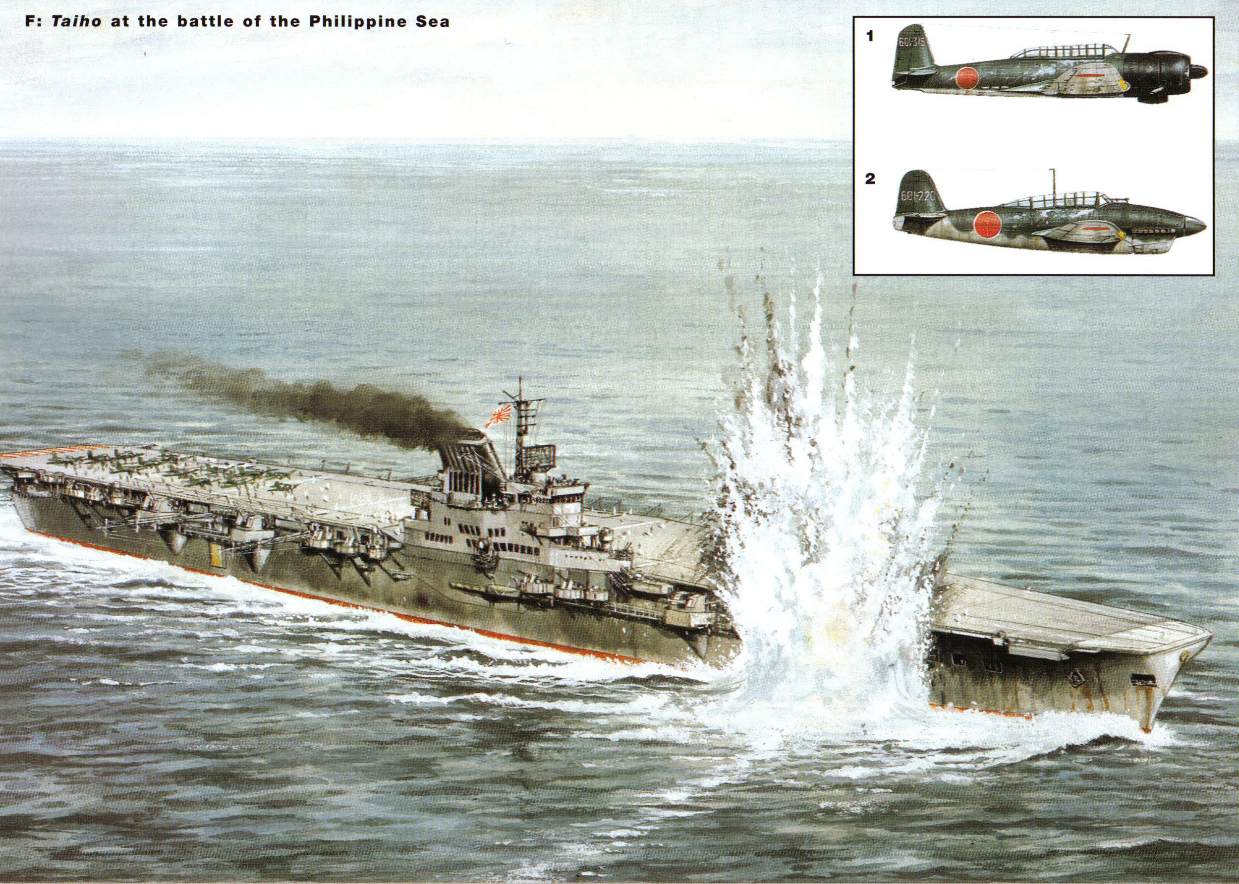
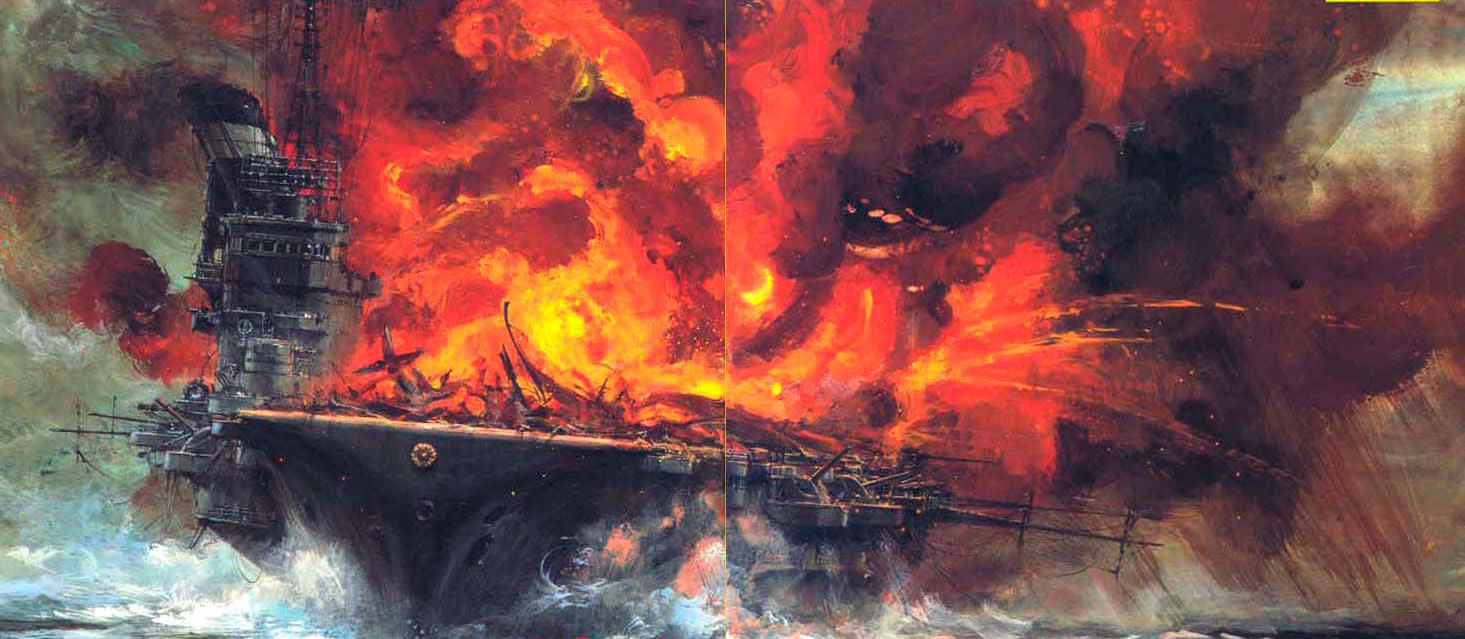
FATE
“Then white bubbles were seen on the surface. Torpedo wakes! The loudspeakers on the bridged blared a command and some of the crew felt cold. Now the wakes of the torpedoes approached the bow. The first passed, the second passed, all passed… but then a water column rose high on the starboard side forward of the island bridge. Some of the bridge personnel got wet and the ship reeled under shock. Torpedo hit! And there was some confusion among crew members”

Once completed, Taiho spent most of her time idly sitting at anchor awaiting the Japanese Admiralty to determine the decisive opportunity to hurl the advancing United States Navy back towards Pearl Harbour.
On the way to the Philippine Sea, she was spotted by the USS Albacore. She sent a volley of six torpedoes heading Taiho’s way.
One of her pilots, having just flown off, saw the torpedoes. Warrant Officer Sakio Komatsu is credited with successfully crashing his Judy aircraft into one of them, preventing it from striking the carrier at the cost of his own life.
One torpedo, however, struck home.
It exploded abreast the forward lift, immediately alongside the forward aviation fuel storage containers.


It was quickly noted the deck of the elevator pit – directly above the forward gasoline tank – was ruptured.
The shock of the explosion had split a joint in the armour above the forward avgas tank. The AvGas tanks themselves were also ruptured, spilling avgas into the surrounding voids. Fuel supply pipes had also been fractured.
A small fire was contained by inrushing seawater as Taiho did not immediately reduce her speed of 27 knots in a bid to escape the submarine threat. Later, Taiho’s captain ordered a reduction of just 1.5kts.
The water flooded into the forward sections of the carrier, causing her to settle by some 5ft by the bows.
The forward lift well quickly filled with a volatile mix of seawater, fuel oil and aviation fuel.
This soon began to vaporise.
Damage control parties knew the danger. They just didn’t know how to deal with it.
Attempts were made to use portable pumps to dump the volatile fuel into the sea. But the nearby foam sprayers were not used to douse the space with an oxygen-reducing, containment coating.
Flight operations were halted due to the forward 100ton lift being jammed (with an A6M5 fighter on it) between the flight and upper hangar decks. It had been at flight deck level, but its cables slackened and part of a pulley broke so it partially collapsed.

Damage control parties quickly plated over the lift well opening (using benches and tables from the mess rooms) in order to allow a further two strikes of aircraft to take-off.
This eliminated the chance for any natural ventilation to force the fumes out of the ship.
An attempt was made to improve airflow through the hangar by opening ventilation ducts on both sides of hangar sections 1 and 2. The aft elevator was also lowered to increase the draft.
It had little appreciable effect, and the lift was soon back in use shifting aircraft.
Then the chief damage control officer ordered all ventilation systems activated and dialled-up to full capacity. He instructed all doors and hatches to the hangar be opened. Crew were ordered to use hammers to smash out glass portholes.
It was exactly the wrong decision.
It allowed the heavy fuel-air mixture to spread throughout the ship.
Six and a half hours after being torpedoed, the inevitable spark happened.
The blast blew out the light hangar walls and part of the ships side hull plating – extending below the waterline. The 'slit' vents in the hangar sides had failed to release the blast's pent-up pressure.
The flight deck armour was also split by the detonation, and many accounts state the heavy steel ‘cap’ served only to deflect much of the blast back down into the bowels of the ship.
But Taiho died hard. It took another hour for the ‘Great Phoenix’ to roll over and plunge to the bottom. Death toll figures vary, from 28 officers and 632 crew to1650 of the 2150 crew reportedly aboard at the time.